LEDster
A portable touchscreen LED strip and fixture tester for field checks, adapter-cable workflows, and repeatable visual tests without relying on venue power or lighting-control networks.
Project snapshot
LEDster is a purpose-built tool for checking LED products away from a full DMX, Art-Net, sACN, or Pixelblaze control setup. It is meant for quick fixture confirmation, cable-end testing, pattern checks, and repeatable setup work.
The current design targets a Waveshare ESP32-P4 touchscreen board with an ESP32-C6 wireless coprocessor, a 4.3-inch capacitive display, a programmable LED output rail, six analog PWM channels, and local direct-pixel output for supported addressable protocols.
Technical highlights
- ESP-IDF firmware for the ESP32-P4 with an LVGL v9 touchscreen interface.
- Single programmable external LED rail,
VLED_OUT, planned around a TPS55288 buck-boost stage. - Six low-side analog PWM channels for non-addressable LED strip testing.
- Direct addressable output paths for GS8208, UCS7604, APA102, HD107, and HD108 families.
- Saved LED, Pixel, Pattern, Test, and Settings profiles stored on microSD.
- WiFi AP file-transfer mode for profile files and staged firmware images.
- Optional Pixelblaze integration path for future local or remote pixel control.
Hardware direction
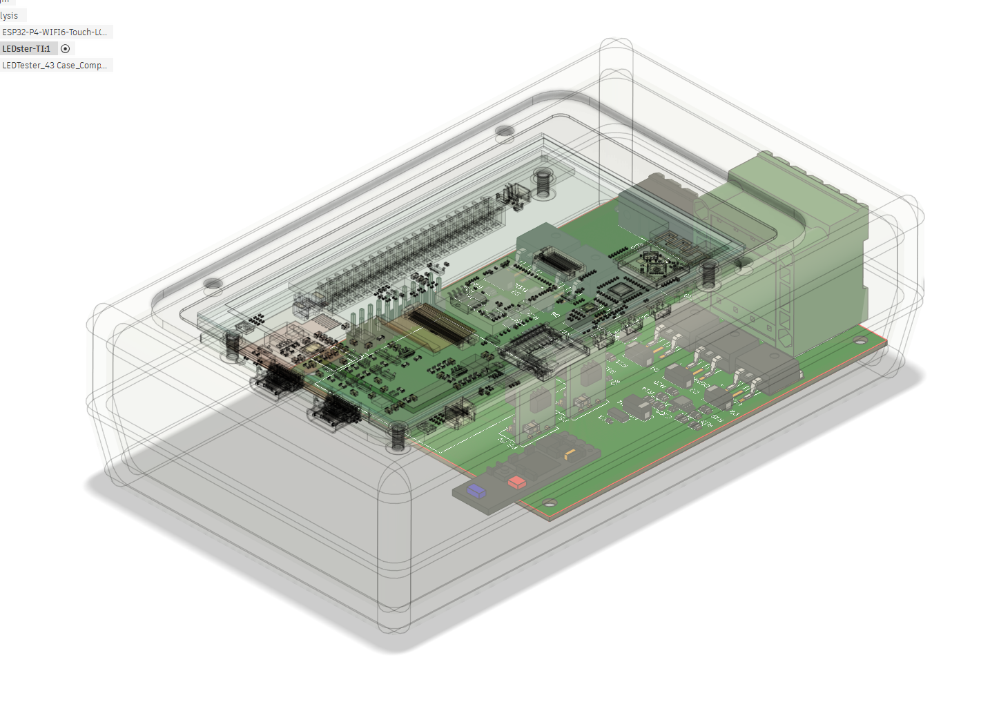
The tester uses adapter cables instead of exposing arbitrary terminals. The tester-side connector stays standardized, while the adapter cable handles the product-specific voltage class, signal wiring, connector style, and labeling.
The current architecture has moved away from separate 5 V, 12 V, and 24 V LED rails. External LED power is planned as one programmable protected output rail, with firmware safety gates around voltage changes, output enable, test start, fault handling, and shutdown.
Development status
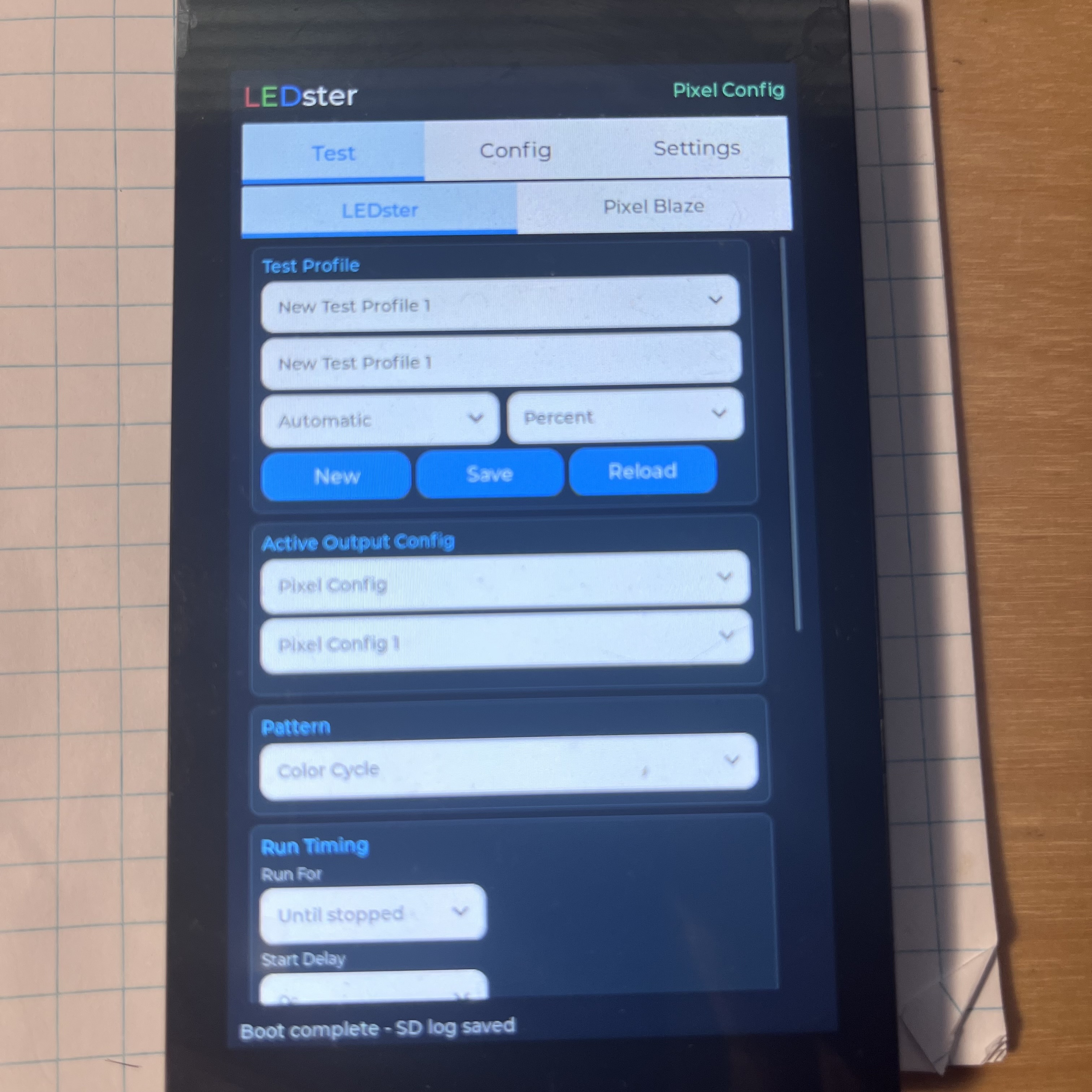
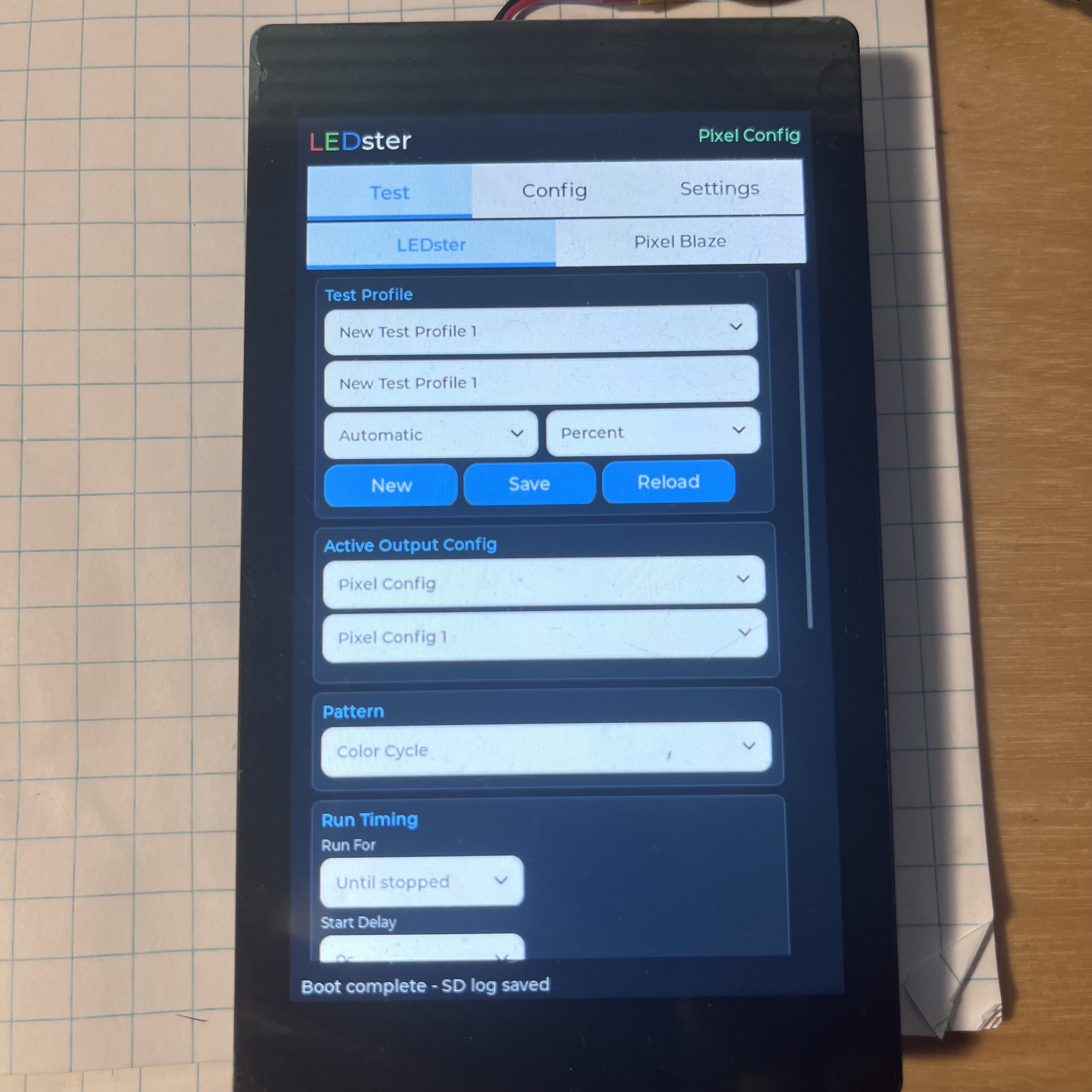
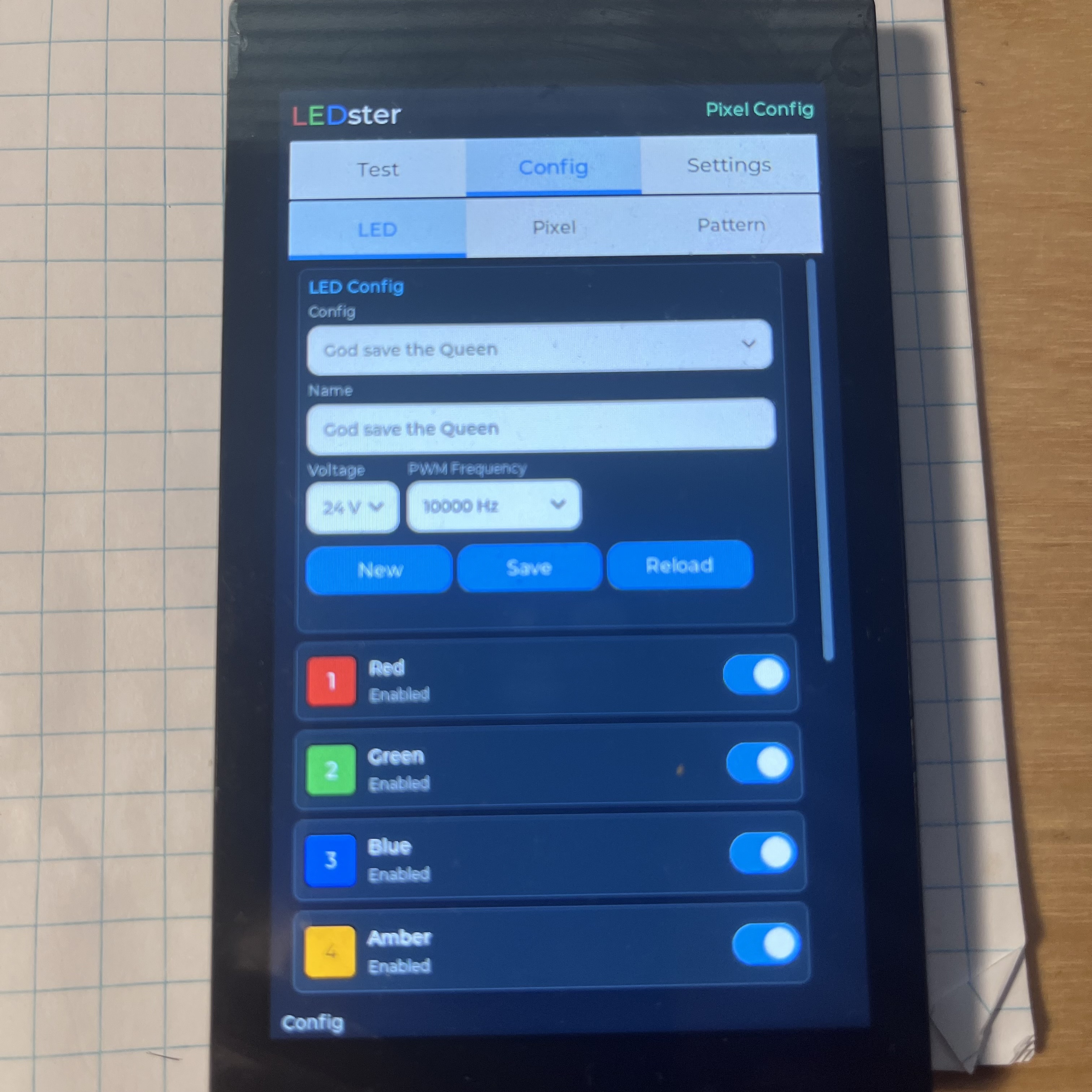
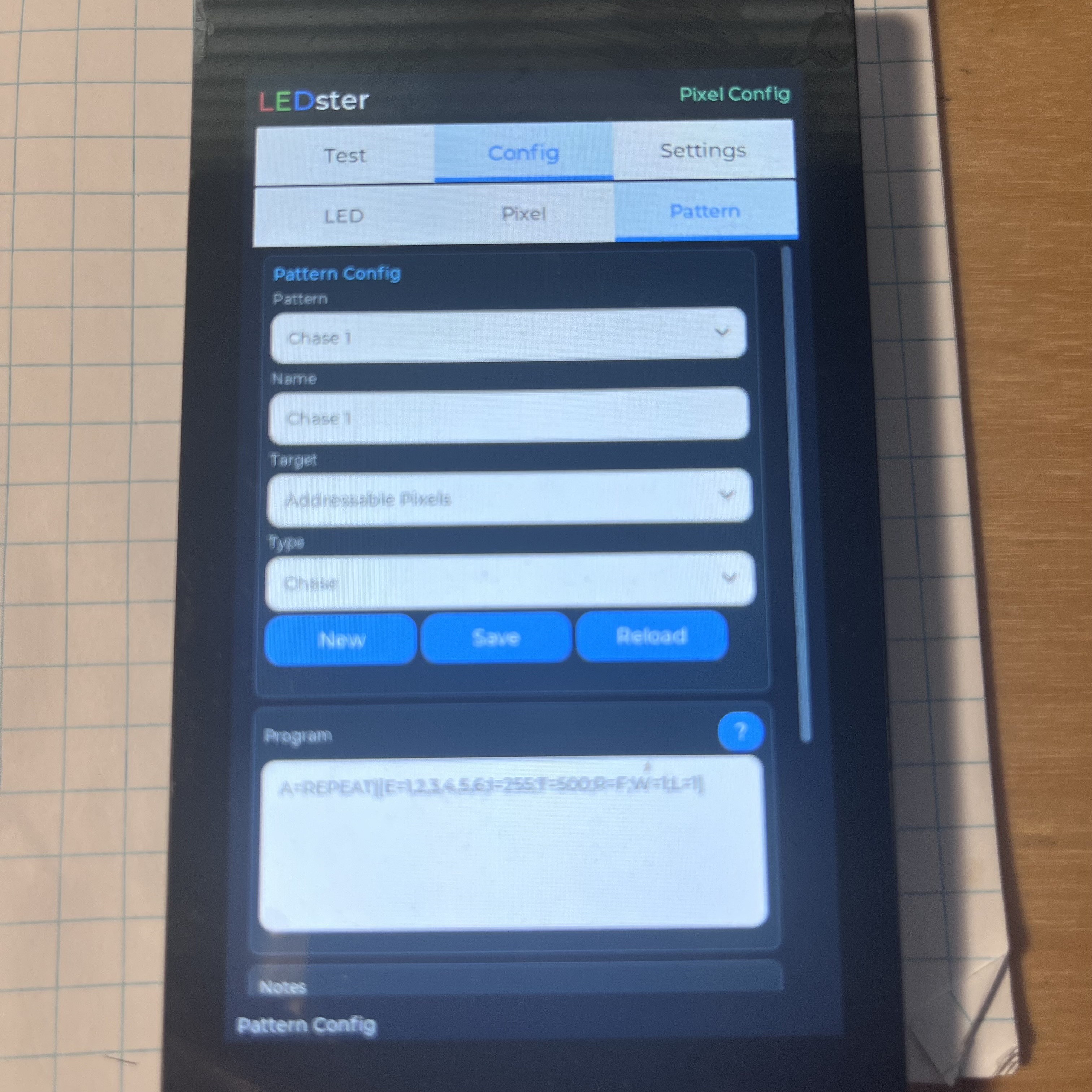
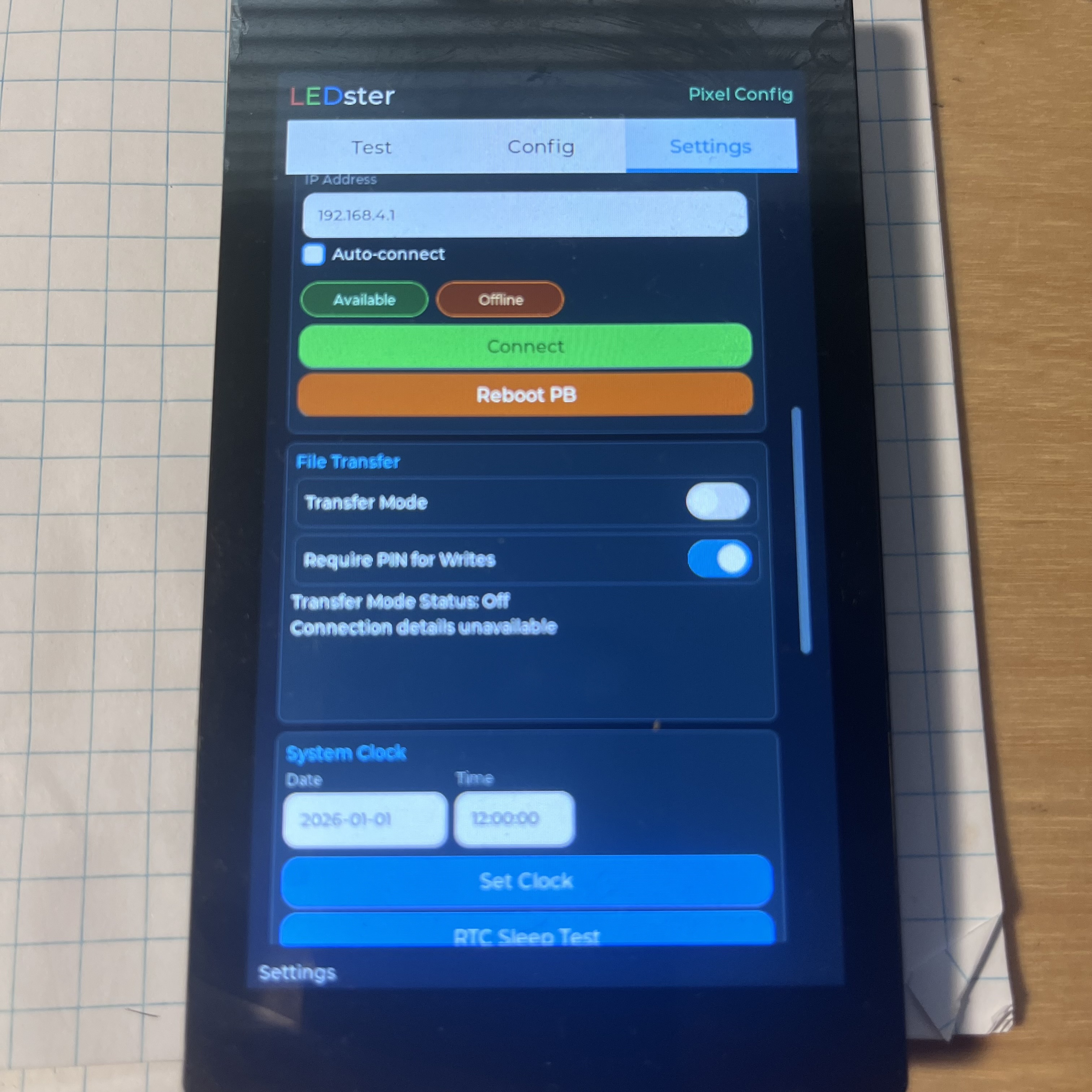
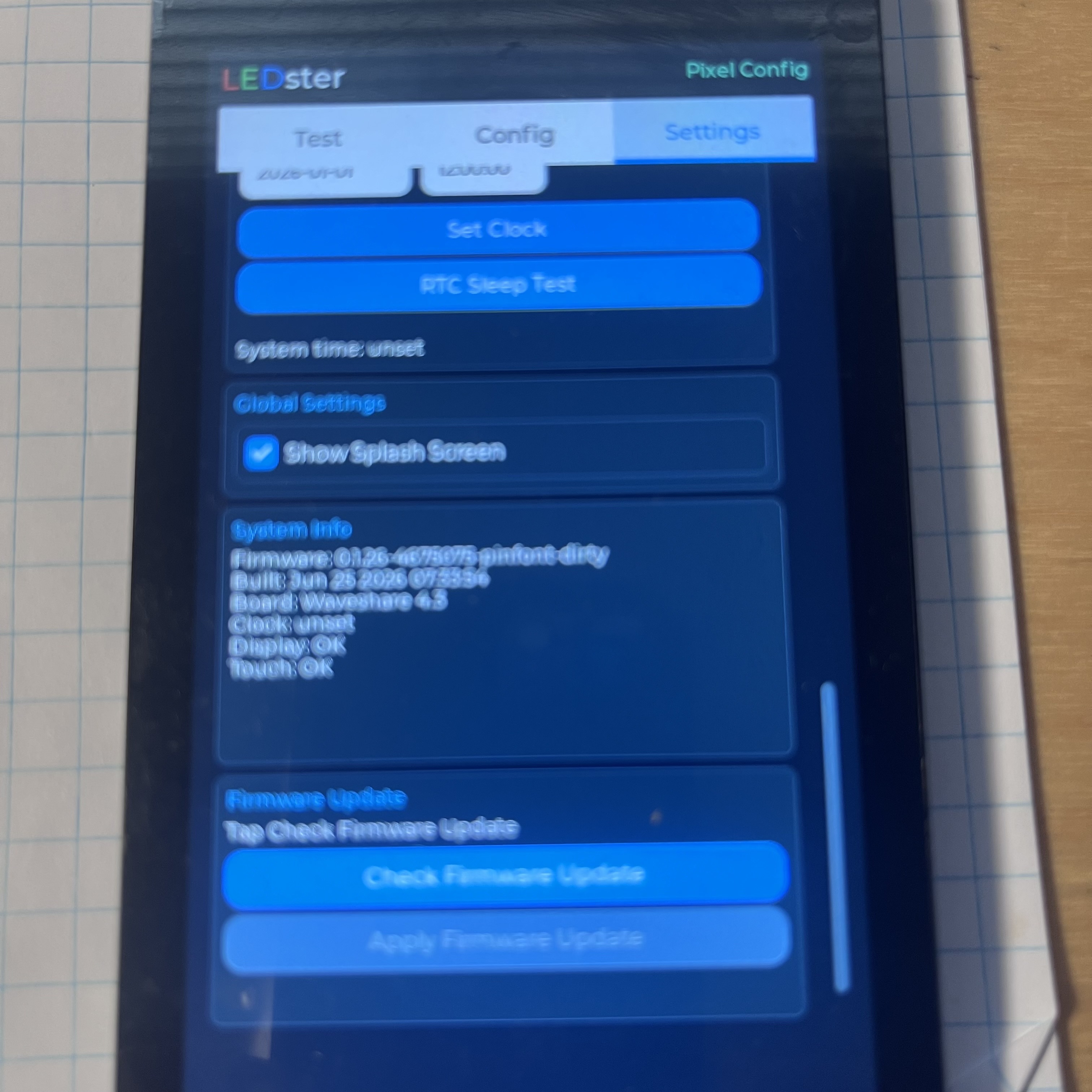
- Touchscreen UI with Test, Config, and Settings areas.
- microSD-backed profile persistence.
- Six-channel analog PWM output verified with representative dimmer values.
- Local direct-pixel firmware paths for the initial supported protocols.
- File-transfer service for profiles and staged firmware updates.
- Final power-rail hardware and output protection.
- Real voltage/current measurement display.
- Hardware validation on representative LED strips and modules.
- Pixelblaze signal-routing hardware and final ownership model.
- Enclosure, battery bay, connector, and adapter-cable refinements.
Media
FIRMWARE_UI — live captures from the touchscreen on the bench
Why it matters
The project combines embedded firmware, power electronics, LED protocol work, product safety, UI design, and field-service thinking. It is less a demo app than a working tool: something that has to be understandable on a touchscreen, hard to misuse, and useful while standing at the far end of a cable run.